Category Archives: Energy technologies

HVAC interlocks

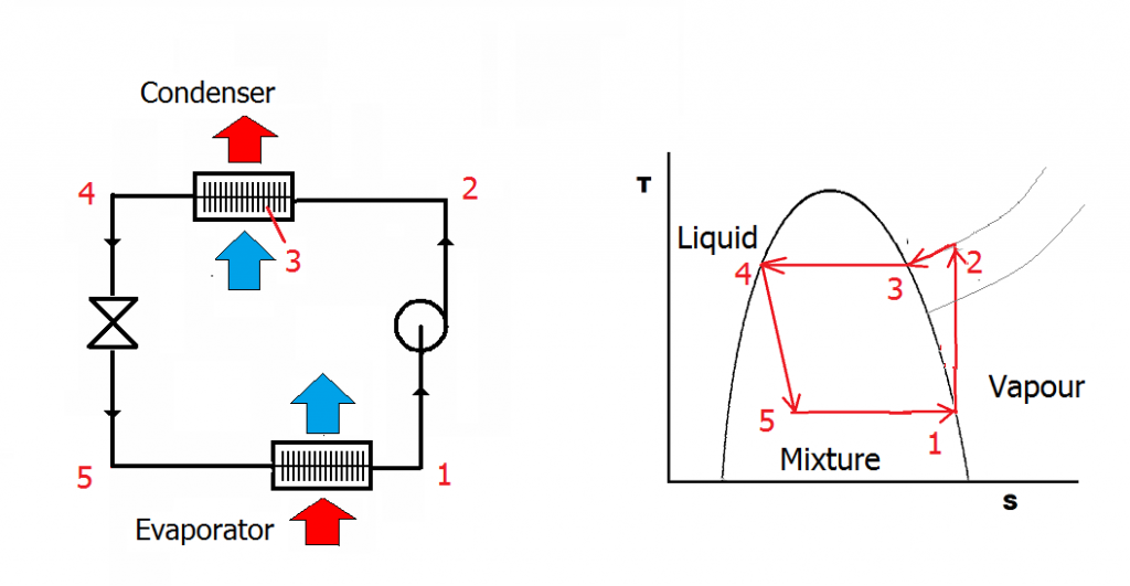
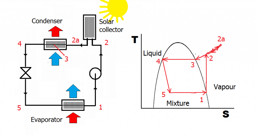
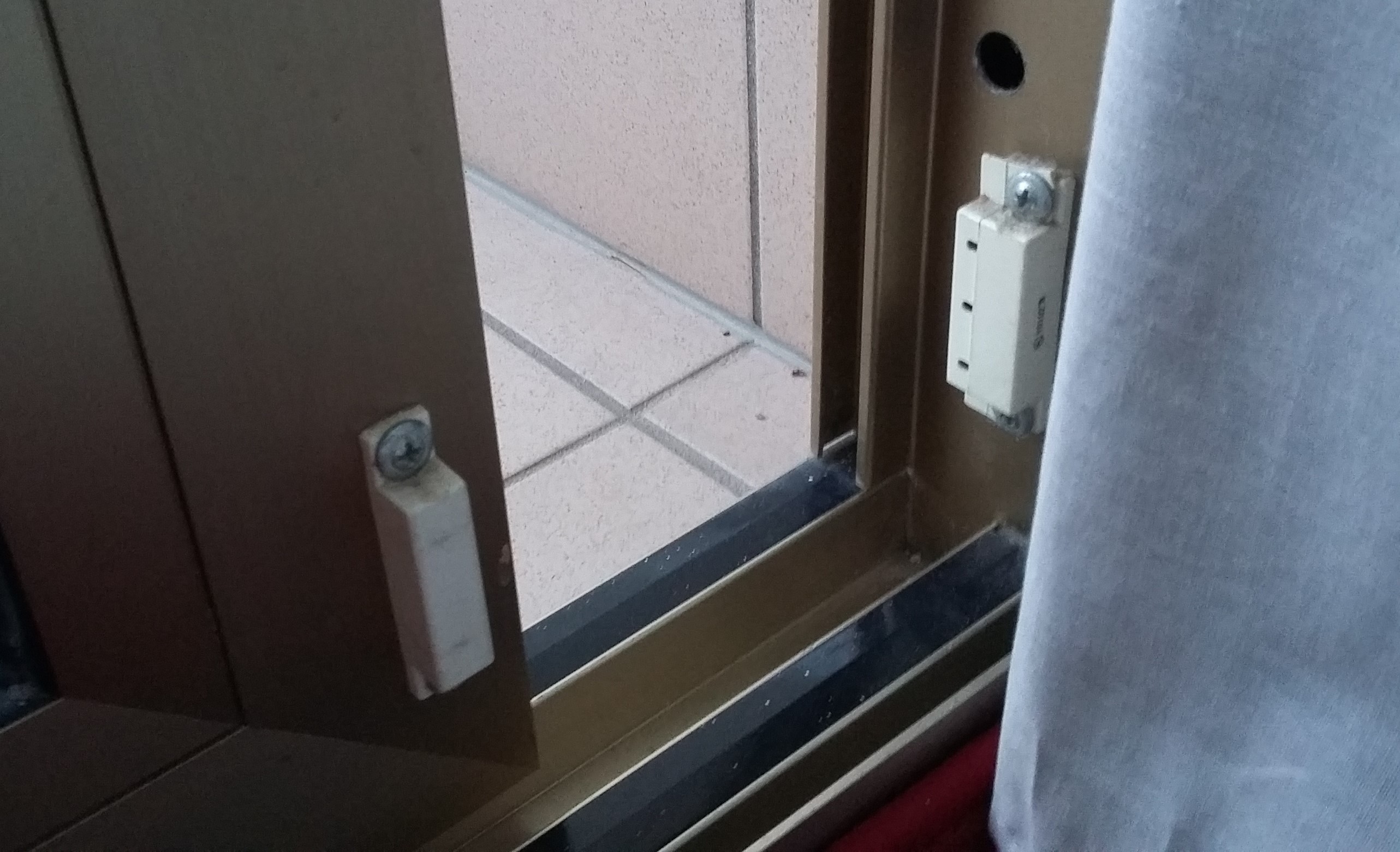
It’s like a curse. Waking up last Wednesday to a view of the full moon reflected off the Adriatic in the pale light of dawn, I opened the sliding door to the hotel balcony to take a snapshot. As I did so I heard the air conditioning fan stop and there in the pale light of dawn I saw a magnetic reed switch on the door frame, evidently linked to the fan-coil unit control. “Brilliant” I thought: “a picture of that will be perfect for my session at our conference on energy in hotels”.

To be fair to myself I did photograph the moonlit Adriatic first and the interlock switch later.


Fuel savings from system water treatment: limits of plausibility

Just how big a saving is it possible to achieve with a product which improves heat transfer in a ‘wet’ heating system (one which uses circulating water to feed radiators, heater batteries or convectors)?  It is an important question to answer because suspect additives claiming to reduce losses through water treatment are becoming prevalent, making claims in the range of 10-20%, while air-removal devices have been claiming up to 30%. It is possible to show that the plausible upper limit is of the order of 7%  and that this would be achievable through good routine maintenance anyway.

To work this out we first break the system into its two major components: the heating boiler (which in reality may be two or more plumbed in parallel) and the building, which represents the heat load. The first thing we can say is that if the heating in the building is maintaining the required temperatures, the thermal load which it presents to the boiler will not be affected by internal heat transfer coefficients. If heat transfer in the heat emitters is impeded, then either the circulating water temperature will rise or control valves will be open for a greater percentage of time in order to deliver the required heat output, or both; either way, the net heat delivered (and demanded from the boiler) is the same.  So water treatments will not affect the heat demanded from the boiler; their only effect will be to improve the efficiency with which the boiler converts fuel into useful heat.  Let us consider how this can be done. Consider the routes by which energy is lost in the boiler:

  1. Standing losses from the boiler casing and associated pipework and fittings;
  2. Sensible heat loss in the exhaust gases. This is the energy that was needed to elevate the temperature of the dry products of combustion (i.e. excluding latent heat);
  3. Latent heat losses, e. the energy implicitly used in converting water to vapour in the exhaust (it is this heat which is recovered in a condensing boiler);
  4. Unburned fuel (carbon monoxide or soot).

Which of these could be affected by water treatment and which would not?  Standing heat loss is sensitive only to the extent that the external surface temperature of the boiler might differ with and without water-side scaling. As such losses would only be about 2% of the boiler’s rated output in the first place, we can safely take the effect of variations to be negligible. Latent heat losses would not be affected because they are solely a function of the quantity of water vapour in the exhaust, and that is fixed by the chemistry of combustion and in particular the amount of hydrogen in the fuel. Unburned fuel losses will not be affected either. They are determined by the effectiveness of burner maintenance in terms of air/fuel ratio and how well the fuel is mixed with the combustion air.

That just leaves sensible heat losses.  Two things can cause higher-than necessary sensible heat loss. One is to have excessive volumes of air fed through the combustion process, and the other is having a higher-than-necessary exhaust gas temperature.  Excess air is self-evidently totally unrelated to poor water-side heat transfer, but high exhaust temperatures will definitely occur if the heat transfer surfaces are dirty or scaled up.  With impaired heat transfer the boiler cannot absorb as much of the heat of combustion as it should, or to look at it a different way, higher combustion-product temperatures are needed to overcome the thermal resistance.

Elevated stack temperature, then, is the only significant symptom of water-side scaling.  So how high could that temperature go, and what are the implications?  Most people would agree that an exhaust temperature of 250°C or more would be highly exceptional and values of 130°C to 200°C more typical.  Now let us suppose for the sake of argument that the exhaust gases in a reasonably well-maintained boiler contain 4% residual oxygen in the exhaust and have a temperature of 130°C, with (to make it realistic) 200 parts per million of carbon monoxide. The stack losses under these conditions will be:

4.2% sensible heat in dry flue gases

11.2% enthalpy of water vapour

0.1% unburned gases.

This leaves a net 84.5% as “useful” heat but we should deduct a further 2% for standing losses, giving 82.5% overall thermal efficiency as our benchmark.

Now let’s suppose that the same boiler had badly fouled heat transfer surfaces, raising the exhaust temperature to 300°C —  way in excess of what one might normally expect to encounter.  Under these conditions the stack losses become:

10.4% sensible heat in dry flue gas

12.7% enthalpy of water vapour

0.1% unburned gases

So we now have only 76.9% “useful” heat which, after again deducting 2% standing losses, means an overall efficiency of 74.9%, compared with the 82.5% benchmark.  The difference in efficiency between the dirty and clean conditions is

(82.5 – 74.9) / 82.5 = 6.8%

and this figure of about 7% is the most, therefore, that one could plausibly claim as the effect of descaling a heating system whose boilers are otherwise clean and reasonably well-tuned. In fact if the observed stack temperature before treatment is lower, the headroom for savings is lower too.  At 200°C the overall efficiency would work out at 81.4% and the potential savings would be capped at about 3%.

Three points need to be stressed here. Firstly, just measuring the flue gas temperature will tell you accurately the maximum that a boiler-water additive alone could conceivably save. Secondly, fireside thermal resistance is orders of magnitude higher so even a relatively huge reduction of waterside resistance will have little impact.

Thirdly, all these potential savings should be achievable just with good conventional cleaning and descaling.


Refrigeration nonsense

The vapour-compression cycle at the heart of most air-conditioning systems consists of a closed loop of volatile fluid. In the diagram below the  fluid in vapour form at (1) is compressed, which raises its temperature (2), after which it passes through a heat exchanger (the “condenser”) where it is cooled by water or ambient air. At (3) it reaches its dewpoint temperature and condenses, changing back to liquid (4). The liquid passes through an expansion valve. The abrupt drop in pressure causes a drop of temperature as some of the fluid turns to vapour: the resulting cold liquid/vapour mixture passes through a heat exchanger (the “evaporator”) picking up heat from the space and turning back to vapour (1).

normal_loop
Figure 1: the vapour-compression refrigeration cycle schematically and on a temperature-entropy diagram

The condenser has two jobs to do. It needs to dump latent heat (3->4) but first it must dump sensible heat just to reduce the vapour’s temperature to its dewpoint. This is referred to as removing superheat.

It has been claimed that it is possible to improve the efficiency of this process by injecting heat between the compressor and condenser (for example by using a solar panel). Could this work?

solar_loop_true
Figure 2: showing the effect of injecting heat

The claim is based on the idea that injecting heat reduces the power drawn by the compressor. It is an interesting claim because it contains a grain of truth, but there is a catch: the drop in power would be inextricably linked to a drop in the cooling capacity of the apparatus. This is because we have now superheated the vapour even more than before, so the condenser now needs to dump more sensible heat. This reduces its capacity to dump latent heat. The evaporator can only absorb as much latent heat as the condenser can reject: if the latter is reduced, so is the former. Any observed reduction in compressor power is the consequence of the cooling capacity being constrained.

The final nail in the coffin of this idea is that reduced power is not the same as reduced energy consumption: the compressor will need to run for longer to pump out the same amount of heat. Thus there is no kWh saving, whatever the testimonials may say.

View a vendor’s response

Effect of voltage on motor efficiency

Proponents of voltage reduction (“optimisation” as they like to call it) have started suggesting that equipment is more energy-efficient at lower voltage. In fact this is quite often not the case. For an electric motor, this diagram shows how various aspects of energy performance vary as you deviate from a its nominal voltage. The red line shows that peak efficiency occurs, if anything, at slightly above rated voltage.

motor_voltage_characteristics

Reduced voltage is associated with reduced efficiency. The reason is that to deliver the same output at lower voltage, the motor will need to draw a higher current, and that increases its resistive losses.

“Look Mum, no hands!”

The striking thing about the plantroom panel switches above is that V-SWITCHHANDthey lack the ‘HAND’ position that is normally provided to allow equipment to run manually, and which are all too frequently found in that condition (right).

If you genuinely need to be able to let people in the plantroom override the automatic control, then at least get your building management system to monitor the switch position to alert you. Otherwise you just end up with stuff running continuously that doesn’t need to.

Cost of steam leaks

2016-01-23 07.53.14How big is my steam leak? The relatively small amount of vapour from this kettle is taking 2.5 kW of power to sustain it, the equivalent of 21,900 kWh per year. If that much energy were delivered by a boiler at 80% efficiency with fuel at say £0.03 per kWh, it would cost over £800 per year.

Now compare this with the size of some of the steam plumes you see around your plant.

Power factor

In electrical power systems using alternating current, the voltage and current can get out of step. This has the effect of reducing the real power in watts; to make up the shortfall the magnitude of the current must increase.

In this six-minute ‘kitchen tabletop talk‘, I try to explain the phenomenon and illustrate it with apparatus made from wire, a spring, string and a chopstick.

Poor power factor wastes energy mainly through excessive losses in transformers and distribution cables. So if you pay for electricity at high voltage and own your own transformers, it definitely pays to do something about poor power factor. But even if you don’t, your electricity supplier will claw back extra money from you through any invoice charges denominated in kVA (kilovolt amperes) or kVAh rather than kWh or kW.

Voltage reduction and cyclical heating

Although it is perfectly true that reducing the supply voltage to an electric heater will reduce its power consumption, this is not the same as saying its energy consumption will decrease. In fact, if it is thermostatically controlled, it will merely run for longer to maintain the energy input needed to balance the thermal energy requirement of the process or space being heated. If the heat output is regulated, energy consumption will not reduce with lower voltage.

But for some heating processes the effect of reduced voltage is actually perverse. For example, consider a laser printer. One of the components in the printer, the fuser unit, contains a heated roller maintained at around 200°C whose job is to melt the toner particles on the paper surface. The heater in the roller is likely to be rated at 500 watts or more, and to minimise energy consumption it is turned off when the printer goes into standby. That is why it can take 20 seconds or so to wake the printer up: the heater element has to boost the roller back up to temperature.

Suppose the element has a resistance of 100 Ω at its normal operating temperature. At 240 V, the current flowing will be 2.4 A (by Ohm’s law) so its power will be 240 x 2.4 = 576 W. Reduce the voltage to 230 V and the current drops to 2.3 A, yielding 529 W, a power reduction of just over 8%.

However, reduced power output means it takes a little longer to reach operating temperature. In the simple simulation illustrated below, the warm-up time increases from 19 to 22 seconds.

laser_printer_warmup

Unfortunately, 22 seconds at 529 watts is 11.6 kJ, whereas 19 seconds at 576 watts (the higher-voltage scenario) is only 10.9 kJ. So the warm-up cycle uses more electricity at lower voltage. Sadly this additional startup energy consumption  is not counteracted by savings elsewhere, since all the other electronic components of the printer will be fed from stabilised power supplies and therefore do not respond to fluctuations in mains voltage.

OK, the energy waste penalty of operating at reduced voltage is absolutely tiny – I quite accept that – but the point is that it is not a saving, let alone a saving of 8%. Furthermore there are plenty of cyclical heating processes from kettles to school pottery kilns where minimising warm-up time will save more than downrating the heater output.


Voltage reduction and IT equipment

The vast majority of computing and communications equipment consists of circuitry that requires very stable supply voltages, usually at 3V, 5V and 12V DC. Because the electronics is supplied at fixed voltage, its power consumption depends entirely on what it is doing and is completely insensitive to mains supply voltage. Fluctuations in mains voltage are dealt with by having stabilised power supply units (PSUs), which these days are commonly engineered to accept AC inputs anything between 100V and 240V while giving the rock-steady DC output that the equipment needs.

psu_efficiencyPSUs are not loss-free. At 87% efficiency, 100W of useful DC output incurs 14.9W of heat loss (100/114.9=0.87). There is much competition between manufacturers to reduce these losses and the sales specification sheets now usually sport a chart like the one above, showing how PSU efficiency changes with loading. Peak efficiency (minimum loss) typically occurs at about half load. But what these charts also disclose is that losses are higher at lower voltage. The difference in this case (230V versus 115V) is extreme, with losses increasing from roughly 15% to 18% as a percentage of output power.

Admittedly a reduction of a few volts would only add a fraction of a percentage point to the PSU losses, but neveretheless although conventional wisdom is that voltage reduction has no effect on energy consumption in computer equipment, the truth is that it should actually incur a slight penalty.

If the IT equipment is in an air-conditioned environment, then what effect will voltage reduction have on chiller power? It depends how it is controlled but either the chillers’ outputs will fall, causing them to run longer to make up the deficit, or their control systems will maintain the requisite output, causing them to demand the same electrical input power. Either way, no saving on input power; you cannot get out more than you put in, and in fact the reduction of condenser cooling fan flow might well compromise the coefficient of performance, causing the chiller installation to use rather more input energy than at the higher voltage.

All in all, not a good prognosis for voltage reduction with IT equipment; and that is without mentioning the fact, often glossed over, that the voltage-reduction gear itself incurs energy losses.